Surface measuring

When talking about measuring a surface, it is likely that it’s roughness is a consideration.

You can also gain an overview of quality assurance for surfaces on the following page. Please contact us if you want to make a request or have any questions.
You can also click directly on one of the sections:

What is surface roughness?

Roughness is a component of surface texture, and is irregularities on a surface resulting from unevenness. These so-called surface deviations arise from the effect a machining or finishing process has on the surface. They are categorised into course and fine. Shape and position deviations are categorised as course form, waviness and roughness are categorised as fine form:

  • Shape: Deviations in long periods or non-cyclical deviations
    Possible causes: Error in the in the machine tool axis, incorrect clamping of the workpiece, uneven wear and tear.
  • Waviness: Surface structure with longer intervals of irregularities.
    Possible causes: Vibration in the machine tool or workpiece. Tooling problems during the manufacturing process of parts.
  • Roughness: Irregularities with shorter intervals
    Possible causes: unwanted rough surfaces are caused by cutting tool markings, grinding wheel/ abrasive grain size.

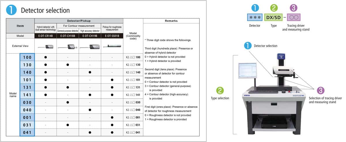
Not sure which measuring instrument fits your needs? Filter by the parameters you need and see the solution that’s right for you. Contact us in terms of questions or requests.

Each manufacturing process affects the surface finish and consequently surface roughness. In order to ensure the quality of the manufactured component despite this, the surface finish is defined according to the so-called roughness value. The actual roughness of the part is determined by measuring the surface profiles with the roughness measuring instrument.
It should be considered that only certain roughness values can be achieved with certain manufacturing processes. These must, therefore, be defined during component design, and according to the specific manufacturing process. Roughness values are therefore defined dependant of the manufacturing process. It is denoted according to the arithmetic mean roughness (Ra) in µm for each manufacturing process.

Factors influencing the surface finish are:

  • Processing:
    • Cutting conditions (cut depth or speed)
    • Tools (cutting, inclination and adjustment angle)
    • Type of work (rotating, grinding, milling)
  • Material (texture)
    • Workpiece stability
    • Cooling lubricant
    • Material cutting properties

Applications

Surface properties can influence the workpiece’s mechanical as well as electrical or chemical behaviour. The roughness of surfaces determines to a large extent their finishes. It is important to characterise surfaces according to their roughness because inspecting the roughness provides opportunities for optimisation. Waviness and course form of the surface must be considered while characterising. Many industries can accordingly profit from inspecting surfaces with roughness measuring instruments, for example:

  • Medical technology:
    By maintaining a certain surface roughness, a dental implant, for example, itegrates into the jaw quicker. The same applies to endoprotheses. Because a prosthetic comes into direct contact with surrounding tissue, its surface quality and surface finish are especially important. Therefore, implant manufacturers try to develop their products as optimally as possible for its intended purpose by using appropriate surface finishes. The average medical component comes with high quality requirements and require very accurate test equipment.
  • Automotive industry:
    A low surface roughness within a drive train reduces friction, whereby energy loss can be kept as low as possible. With high demands for efficiency, the requirements on the surfaces of cranksheft bearing pins also increase. With the start-stop systems that automatically turn off the engine and back on again, a lot of strain is, for example, put on the surface of the pin. Here, a lower surface roughness reduces wear and tear. For electric motors, surface roughness also plays a roll in reducing noise. Here, the smoothest surface finish possible is needed, and is why the surface quality must be ensured, and validated using roughness measuring.
  • Electronics and semiconductors:
    Microchips must always be smaller, faster, and more effective. These challenges require observing geometric tolerances on each component, such as coplanarity, distance, warpage, and volume as well as roughness parameters, which require extremely high resolution at the nano level on average. For this reason, they are often measured with optical surface measuring systems and the success lies in non-contact measurement.

We offer roughness and contour measuring instruments as well as combined roughness/contour measuring instruments for the most diverse range of demands such as surface finish or defining rough surfaces. With our Product Finder, you can easily and quickly find the right surface measuring instrument for your needs.
We would gladly set up a consultation and a demonstration with you.

Roughness measuring

Roughness measuring of a surface allows a workpiece to be evaluated regarding its function, quality and wear behaviour. In order to inspect the surface quality of a workpiece, various roughness measuring methods are applied, which can be classified roughly into subjective and objective measuring methods:

  • Subjective methods include visual and haptic inspection by feeling and observing the workpiece. Visual inspection is often also the first step before employing a roughness measuring instrument. Because the visual examination is predominately carried out by people, it is liable, therefore, to be less efficient compared with automated inspections. The reasons for this are, for example, concentration fluctuations, performance pressure, fatigue, environmental influences, etc.
  • For objective surface roughness measuring methods, tactile or optical measuring instruments with micrometre or nano range are employed. To finish the quality control correctly and precisely, rough surfaces need to be analysed with the correct software. Measuring methods allows for a 2D or 3D (topography) analysis according to the measuring system. Measuring data can be recorded, saved and analysed and are suited for statistical analyses.

To metrologically record and define the surface roughness, the profile method is applied. With the profile method, a stylus tip traverses across a workpiece’s surface at a constant speed. With the tacticle measuring method, the roughness measuring instrument’s sensor scans the surface bit by bit. Here, waviness and course form can be monitored and defined. With values at nano- and micrometer levels, the precision of the tactile measuring system for roughness measuring is very high. They are often simple to use and provide reliable measurement values. They are, however, not appropriate for soft, yielding surfaces because damage to the surface cannot be ruled out with tactical roughness measuring instruments. Therefore, for this, increased optical three-dimensional measuring processes are employed that measure the surfaces without contact and are, therefore, non-destructive. Applications have irregularities such as waviness or course form which leads to specific measurement requirements. On average, systems need to have a nano- or micrometre range to characterise rough surfaces.

Measurement process for roughness measuring instruments

The exact process for surface roughness measuring with a tactical surface measuring instrument is explained in ISO 4288:1996. To prepare for roughness measuring, we recommend the following approach:

  1. Clean the workpiece and position it stably.
  2. The measuring system must be calibrated and the correct stylus-arm combination attached.
  3. The workpiece should be set up so that and the direction of the surface structure grooves are aligned at a right angle to the measurement direction.
  4. If the profile cut-off filter λc and evaluation length are not specified for measuring the roughness parameters, you can, according to the table ISO4288  choose the configurations.
  5. Configure the necessary profile filters (λc and λs for roughness). (This is normally the Gaussian filter).
  6. Choose the necessary surface parameters.
  7. Measure and determine the measurement values.
  8. To finish the process, compare the measurement results with those of the permissible number values specified in the technical documentation.
Table: choose the right stylus tip to measure surface roughness

According to DIN EN ISO 4288, the roughness profile must be measured in 5 sampling lengths. The majority of roughness parameters – such as arithmetic mean roughness (Ra), mean roughness depth (Rz), or maximum roughness depth (Rmax) – are calculated across the sampling length. Parameters, such as material ratio (Rmr) or total depth (Rt) of the roughness profile, can be observed across the entire roughness profile.

We offer roughness and contour measuring instruments as well as combined roughness/contour measuring instruments for the most diverse range of demands such as surface finish. With our Product Finder, you can easily and quickly find the right surface measuring instrument with nano- or micrometre range for your needs. We would gladly set up a consultation and a demonstration with you.

Definition of measurement lengths

  • Sampling length (Ir): The length of the sampling length is numerically the same as the upper wavelength limit. (lr = λc , lw = λf).
  • Measured length (In): The measured length (In): is the sum of the sampling lengths (I). It includes at least one sampling length, however it usually includes five.
  • Traverse length (It): The length covered during the scanning system measuring process. It includes the measured length (In) as well as the start-up and trailing length (filter’s outward oscillation and stabilisation length), which equates to the entire or half of the sampling length. For highly precise measuring systems, up to one third of the sampling length.
Technical drawing of profile roughness parameters: sampling lenghth and evaluating length

Surface quality parameters

In contrast to dimensional measurement quantities, such as length, surface roughness measurement quantities are not clearly defined. Therefore, there are various roughness measurement values for assessing surface finish that are used in design drawings by means of abbreviations. The most significant roughness parameters, according to the international standard DIN EN ISO 4287, that the classic profile method employs, are:

  • Ra: The internationally used roughness parameter is defined as an arithmetical mean of the absolute profile deviation value within the defined length.
  • Rmr(c): The (percentage) profile material ratio is defined as the quotient of the sum of the material lengths of the profile elements in the given cut height c (in μm) and the measured length (In).
  • RSm: The average groove width describes the width mean of the profile elements (Xs). Horizontal and vertical counting thresholds are set for analysis.
  • Rt: The abbreviation stands for “Total Roughness Profile Height” and is the sum of the heights (Zp) of the largest profile peak and the depths (Zv) of the largest profile valley within the measured length (In).
  • Rzi: The roughness parameter stands for the highest roughness profile and is the sum of the heights of the largest profile peak and the depths of the largest profile valley within the sampling length (Iri).
  • Rz1max: This is the maximum roughness depth and therefore, the largest of the five Rzi values from the sampling lengths (Iri) within the measured length (In).
  • Rz: The average roughness depth is defined by the five Rzi values from the sampling lengths (Iri) within the measured length (In).
Technical drawing: surface profile by stylus and gaussian filter

Factors influencing measurement results

When you measure surface roughness, the measurement results can be influenced by many factors. These can be summarised as follows:

  • Environment (environmental factors in production): For example, temperature fluctuations during roughness measuring can influence the result. Humidity or vibration can also have an effect on the measurement results.
  • Measuring strategy, such as selection of measuring methods and probes
  • People: The experience of the metrologist also affects the measurement results.
  • Measurement object: How clean is the surface?
  • Measuring instrument: The easier a roughness measuring instrument is to handle, the lower the chance of measuring errors. Additionally, the choice of roughness measuring instrument can increase preciseness, such as the SURFCOM Series with its linear drive that drastically reduces vibration and facilitates a higher positioning accuracy.